Sequential System Design
Expert Answer & Key Takeaways
Master memory-based digital circuits, including Flip-Flops, Shift Registers, and Synchronous/Asynchronous Counters.
Sequential System Design
Unlike combinational circuits, where the output is determined solely by the current inputs, Sequential Logic Circuits have memory. The output of a sequential circuit depends on both the present inputs and the past sequence of inputs (the current state). To retain past information, sequential circuits employ memory elements (latches or flip-flops) and feedback loops where the output is routed back to the input.
1. The Clock Signal & Triggering
A clock is a periodic square wave signal that synchronizes the state changes of sequential circuits.
- Latches (Level-Triggered): State changes occur continuously as long as the clock/enable signal is at a specific voltage level (HIGH or LOW). Latches are transparent.
- Flip-Flops (Edge-Triggered): State changes occur only at the exact moment the clock transitions from LOW to HIGH (Positive Edge) or HIGH to LOW (Negative Edge). This precise timing prevents unstable feedback loops.
2. Flip-Flops (The Memory Building Blocks)
Flip-flops are 1-bit memory storage devices. There are four fundamental types. In competitive exams, you must memorize their Characteristic Equations (which predict the next state based on the inputs and the present state ).
2.1 SR (Set-Reset) Flip-Flop
The basic memory cell.
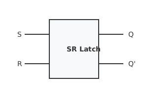
- S = 1, R = 0: Sets the output to $1$.
- S = 0, R = 1: Resets the output to $0$.
- S = 0, R = 0: Memory state (Holds ).
- S = 1, R = 1: Invalid/Forbidden state (causes unpredictable behavior).
- Characteristic Equation: (Valid only if )
2.2 D (Data / Delay) Flip-Flop
Created by adding an inverter between the S and R inputs. It ensures that S and R are never equal, eliminating the invalid state. The output simply follows the input at the clock edge.
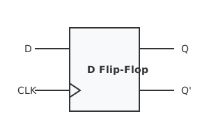
- Characteristic Equation:
2.3 JK Flip-Flop
An improvement over the SR flip-flop. It behaves identically to the SR flip-flop, except it defines the $1, 1$ input condition as a Toggle state rather than an invalid state.
- J = 1, K = 1: Toggles the output ().
- Characteristic Equation: The Race-Around Condition: In a level-triggered JK Latch, if , the output will continuously toggle back and forth as long as the clock is HIGH, leading to an unpredictable final state. This is called the Race-Around condition. It is solved by using Edge-Triggering or a Master-Slave configuration.
2.4 T (Toggle) Flip-Flop
Created by tying the J and K inputs together. It is used primarily in frequency dividers and counters.
- T = 0: Memory state.
- T = 1: Toggles the state.
- Characteristic Equation:
3. Shift Registers
A register is a group of cascaded flip-flops used to store or shift multiple bits of data. Shift registers move data laterally through the flip-flops on every clock pulse.
Classification by Input/Output:
- SISO (Serial-In, Serial-Out): Data enters one bit at a time and exits one bit at a time. Acts as a time delay.
- SIPO (Serial-In, Parallel-Out): Converts a serial data stream into a parallel format.
- PISO (Parallel-In, Serial-Out): Converts parallel data into a serial stream (e.g., for UART transmission).
- PIPO (Parallel-In, Parallel-Out): Standard memory buffer. Fastest read/write.
4. Counters
Counters are sequential state machines that cycle through a predetermined sequence of states upon receiving clock pulses. A counter with flip-flops can count up to a maximum of states. The total number of states is called the Modulus (MOD).
4.1 Asynchronous (Ripple) Counters
The external clock is applied only to the first flip-flop (LSB). Subsequent flip-flops are clocked by the output of the preceding flip-flop.
- Advantage: Simple hardware design.
- Disadvantage: Slower. The propagation delays of each flip-flop add up (ripple effect). The maximum clock frequency is limited by
4.2 Synchronous Counters
The external clock is applied simultaneously to all flip-flops in the counter.
- Advantage: Extremely fast, as there is no cumulative propagation delay.
- Disadvantage: Complex combinational logic is required to determine the inputs for each flip-flop.
4.3 Special Shift-Counters
- Ring Counter: A circular shift register where the output of the last flip-flop is fed directly back to the first. If initialized with a single '1', it acts as a sequencer. MOD = .
- Johnson (Twisted-Ring) Counter: The inverted output of the last flip-flop is fed back to the first. MOD = .
Course4All Editorial Board
Verified ExpertSubject Matter Experts
Comprising experienced educators and curriculum specialists dedicated to providing accurate, exam-aligned preparation material.
Pattern: 2026 Ready
Updated: Weekly
Found an issue or have a suggestion?
Help us improve! Report bugs or suggest new features on our Telegram group.