Combinational Logic Design
Expert Answer & Key Takeaways
Comprehensive guide to combinational circuits including Adders, Subtractors, Multiplexers, Encoders, and Decoders.
Combinational Logic Design
Digital circuits are broadly classified into two categories: Combinational and Sequential. A Combinational Logic Circuit is a circuit whose present output depends strictly on its present inputs at any given instant of time. It contains no memory elements (flip-flops) and no feedback loops.
1. Arithmetic Circuits
Arithmetic circuits are the building blocks of the Arithmetic Logic Unit (ALU) inside a CPU. They perform basic binary addition and subtraction.
1.1 The Half Adder
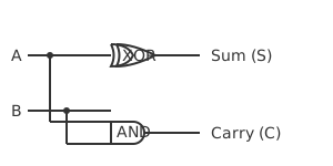
A Half Adder is a combinational circuit that adds two single-bit binary numbers ( and ). It produces two outputs: a Sum () and a Carry (). It is called a "half" adder because it cannot accept a carry-in from a previous lower-order bit addition.
Truth Table:
| A | B | Sum () | Carry () |
|---|---|---|---|
| 0 | 0 | 0 | 0 |
| 0 | 1 | 1 | 0 |
| 1 | 0 | 1 | 0 |
| 1 | 1 | 0 | 1 |
| Boolean Expressions: |
- Sum: (XOR operation)
- Carry: (AND operation)
1.2 The Full Adder
A Full Adder adds three single-bit numbers: two operand bits ( and ) and a carry-in bit () from a previous stage. It produces a Sum () and a Carry-out ().
Boolean Expressions:
- Sum:
- Carry-out: Hardware Implementation: A Full Adder can be constructed logically by cascading exactly two Half Adders and one OR gate.
2. Data Routing: Multiplexers and Demultiplexers
2.1 Multiplexer (MUX)
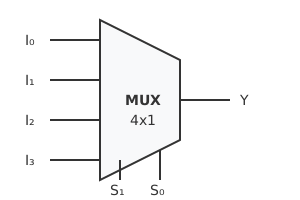
A Multiplexer (often called a Data Selector) is a combinational circuit that selects binary information from one of many input lines and directs it to a single output line.
Architecture:
A MUX has data inputs, selection lines, and exactly $1$ output. The selection lines determine which specific input gets routed to the output.
Boolean Expression for a 4-to-1 MUX ( are selection lines):
 Universal Implementation (GATE Concept):
A Multiplexer is considered a universal combinational block. Any Boolean function of variables can be implemented using a single -to-1 MUX.
Universal Implementation (GATE Concept):
A Multiplexer is considered a universal combinational block. Any Boolean function of variables can be implemented using a single -to-1 MUX.
Universal Implementation (GATE Concept):
A Multiplexer is considered a universal combinational block. Any Boolean function of variables can be implemented using a single -to-1 MUX.2.2 Demultiplexer (DEMUX)
A Demultiplexer (Data Distributor) performs the exact opposite function of a MUX. It takes a single input line and routes it to one of possible output lines based on the state of selection lines.
3. Encoding and Decoding Circuits
3.1 Decoder
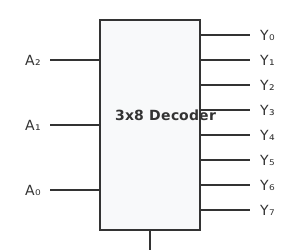
A Decoder is a combinational circuit that converts binary information from input lines to a maximum of unique output lines.
Minterm Generator:
In digital logic, a decoder essentially generates all possible minterms of the input variables. If an Enable (E) pin is present and active, exactly one output line corresponding to the binary value of the input will be HIGH ($1$), while all others remain LOW ($0$).
3.2 Encoder
An Encoder is the inverse of a decoder. It has up to input lines and output lines. It generates the binary code corresponding to the input line whose state is active (HIGH).
Priority Encoder:
In a standard encoder, if two inputs are active simultaneously, the output is undefined (erroneous). A Priority Encoder solves this by assigning priority to the inputs. If multiple inputs are HIGH, the encoder outputs the binary code of the active input with the highest designated priority.
Course4All Editorial Board
Verified ExpertSubject Matter Experts
Comprising experienced educators and curriculum specialists dedicated to providing accurate, exam-aligned preparation material.
Pattern: 2026 Ready
Updated: Weekly
Found an issue or have a suggestion?
Help us improve! Report bugs or suggest new features on our Telegram group.